Vapor Recovery Unit Troubleshooting: Causes of High Tank Pressure, Low Recovery, and Frequent Shutdowns
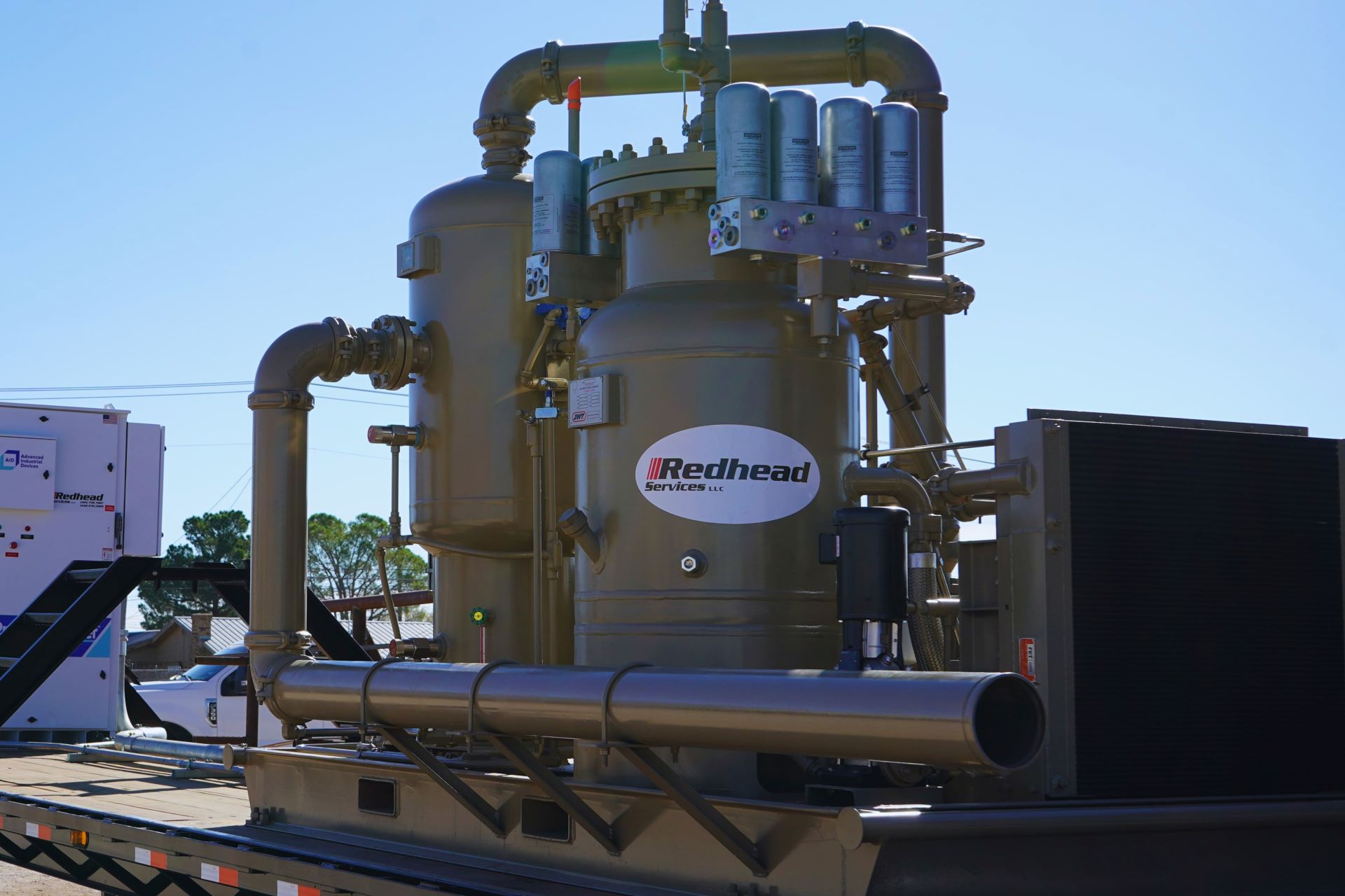
When a vapor recovery unit cannot hold tank pressure, recover the expected volume, or stay online, the compressor itself is only one possible cause. The problem can begin in the tanks, vapor header, separator, discharge system, controls, or the operating assumptions used to select the package.
Effective troubleshooting starts with the symptom, the shutdown history, and process data from before the problem appeared. This guide provides a field-oriented sequence for narrowing the cause. Follow site safety procedures, respect hazardous-area requirements, isolate energy before opening equipment, and use the manufacturer’s instructions and qualified personnel for testing or repair.
Before Adjusting Anything, Capture the Evidence
Do not immediately change pressure setpoints, bypass shutdowns, or increase speed. Those actions can hide the original condition or move the problem somewhere more dangerous. Record:
- Tank and header pressure before, during, and after the event
- VRU suction and discharge pressure and temperature
- Compressor speed, load, valve position, current, or engine data as applicable
- Separator or scrubber levels and drain activity
- Alarm and shutdown codes in their original sequence
- Production rate, fluid transfer events, separator dumps, and recent well changes
- Weather and ambient temperature
- Recent maintenance, control changes, piping changes, or gathering-pressure changes
A trend is more useful than a single reading. If the control system records data, compare a stable period with the period leading to the fault.
Symptom 1: High Tank or Vapor-Header Pressure
The vapor load is higher than the VRU can handle
Tank vapor generation changes with oil rate, fluid temperature, separator pressure, flashing, working and breathing losses, and transfer activity. New wells, increased production, warmer weather, a higher separator dump rate, or tying additional tanks into the header can push the vapor load beyond the original design case.
Compare current operating conditions with the data used to size the unit. If pressure rises during repeatable production or transfer events while the compressor is already at maximum useful capacity, the package or control strategy may be undersized for the current peak—even if average daily recovery appears acceptable.
The suction path is restricted
A compressor cannot control tank pressure if vapor cannot reach it. Inspect the full path for closed or mispositioned valves, plugged flame arrestors or filters, collapsed or liquid-filled low points, undersized headers, failed pressure-vacuum devices, ice, wax, debris, and unintended pressure drop through fittings or long piping runs.
Compare pressure at the tanks, along the header, and at the VRU suction. A meaningful pressure difference identifies where to focus. Confirm instrument accuracy before treating the readings as definitive.
Air is entering the vapor system
Leaks on a system operating below atmospheric pressure can admit air. That adds volume the compressor must move and can create an unsafe mixture. Possible entry points include tank hatches, thief hatches, open drains, worn seals, leaking gaskets, and improperly set pressure-vacuum equipment.
If air ingress is suspected, follow the facility’s gas-testing and shutdown procedures. Do not continue operating by simply increasing capacity. Find and correct the leak and verify the oxygen-control or shutdown strategy.
The compressor is not delivering expected capacity
Low speed, unloaded cylinders, leaking valves, worn components, belt slip, inadequate driver power, high suction temperature, recycle leakage, or a control output limit can reduce capacity. Compare actual speed, load, valve positions, and pressures with the expected operating point and the package performance data.
Symptom 2: Low Vapor Recovery
Discharge pressure has increased
Higher gathering or sales-line pressure raises compression ratio and reduces the capacity available from many compressor configurations. It can also increase discharge temperature and driver load. A package that met the original duty may recover less gas after downstream pressure changes.
Measure pressure at the package discharge and at the final tie-in while the unit is loaded. Check valves, coolers, meters, check valves, and piping for restrictions. If the gathering system regularly operates above the original design pressure, the application needs to be reevaluated rather than repeatedly resetting trips.
Recycle or bypass flow is masking net recovery
A recycle valve that is open, leaking, incorrectly calibrated, or commanded by the control logic can make the compressor appear loaded while much of the gas returns to suction. Confirm commanded position and actual position, inspect the valve, and distinguish compressor throughput from net gas delivered downstream.
The flow measurement is wrong
Before concluding that recovery fell, validate the measurement. Check meter range, pressure and temperature compensation, transmitter scaling, gas composition, calibration status, and whether the reported value represents instantaneous, daily, standard, or actual volume. Compare against a second defensible measurement where possible.
Mechanical condition has degraded
Valve leakage, ring wear, damaged packing, seal leakage, fouled coolers, restricted filters, and driver problems can reduce performance gradually. Review maintenance history, operating temperatures, vibration, leakage, and capacity trends. Use manufacturer-approved diagnostic methods; opening process equipment requires isolation, depressurization, and gas-free verification under site procedures.
Symptom 3: Frequent VRU Shutdowns
High suction-scrubber level
Liquid carryover is a common source of VRU trips. The upstream process may be sending slugs, vapor may be condensing in the header, an automatic drain may be blocked or gas-bound, the drain destination may be pressurized, or the level instrument may be faulty.
Determine whether liquid is actually present before assuming an instrument problem. Review drain operation, piping slope, low points, heat tracing, separator performance, and the timing of trips relative to tank or separator events. Never defeat a high-level shutdown to keep a compressor running.
High discharge temperature
High compression ratio, high suction temperature, cooler fouling, failed fans, restricted airflow, low lubricant level, incorrect unloading, gas-composition change, or operation outside the intended map can raise discharge temperature. Confirm the temperature with a reliable instrument and inspect cooling airflow, cooler condition, fan operation, and stage pressures.
High discharge pressure
A closed valve, plugged cooler or filter, failed check valve, restricted sales line, or rising gathering pressure can produce a high-discharge trip. Verify valve lineup and compare pressure at several points. Do not raise the shutdown setting without confirming the equipment and piping ratings and the reason the pressure changed.
Low suction pressure or rapid cycling
If the unit removes vapor faster than the tanks generate it, suction pressure can fall to a stop point and then rise again, causing repeated starts. Oversizing, a narrow start-stop band, poor pressure-transmitter location, excessive control delay, or inadequate turndown can cause this pattern.
Review trends and the intended control philosophy. The answer may be control tuning, a different capacity-control method, or package reconfiguration—not a wider pressure band that conflicts with tank limits.
Controls, power, or instrumentation are unstable
Loose wiring, poor grounding, weak batteries, inconsistent fuel, voltage dips, failed solenoids, noisy pressure signals, moisture in instrument air, communication faults, and intermittent sensors can all mimic a process problem. Use the alarm sequence and input trends to identify whether a shutdown command was legitimate. Test instruments through approved procedures rather than bypassing protective inputs.
Gas Composition Can Change the Diagnosis
Changes in molecular weight, heavier hydrocarbons, carbon dioxide, hydrogen sulfide, water, or oxygen affect required power, temperatures, condensation, materials, safety, and the relationship between measured volume and mass flow. A gas analysis from initial startup may no longer represent a site after new wells or process streams are connected.
Obtain a representative current analysis when performance has shifted without an obvious mechanical cause, when liquid formation increases, or when the unit is being asked to serve a new source. Share both the original and current analysis during an application review.
A Practical Troubleshooting Sequence
- Make the condition safe. Respond to alarms, tank pressure, gas detection, liquids, and failed ignition or power according to site procedures.
- Preserve the alarm sequence and trends. Avoid resetting before recording the evidence.
- Verify instruments. Confirm the key pressure, temperature, level, and flow readings.
- Check the process path. Review tank conditions, vapor headers, valve lineup, scrubbers, drains, and discharge restrictions.
- Compare current conditions with the design basis. Look for changes in rate, pressure, composition, liquids, ambient temperature, or connected equipment.
- Check controls and mechanical performance. Confirm speed, load, recycle, cooling, power, alarms, and maintenance condition.
- Correct the root cause and verify under load. Trend the system through the event that originally caused the problem.
When the VRU Needs Reconfiguration
Maintenance restores equipment condition; it does not change the operating envelope. Request a new application review when:
- Current or peak vapor load exceeds the original cases
- Tank or suction pressure must operate outside the original range
- Gathering pressure has materially increased
- New tanks, wells, separators, or vapor sources have been connected
- Gas composition or liquid loading has changed
- The unit spends excessive time recycling, unloaded, or cycling
- Cooling, driver power, cylinder displacement, or control range is consistently limiting
- Protective trips recur after instruments and mechanical condition are verified
Possible solutions may include control changes, revised piping, better liquid separation, different driver or compressor configuration, added cooling, a parallel unit, or replacement with a package sized for the new duty. The right answer depends on measured operating cases.
Bring Data to the Service Call
Redhead Services provides configurable vapor recovery units, application guidance, and field support across our West Texas and Southeast New Mexico service area. For faster troubleshooting, gather the alarm history, pressure and temperature trends, current gas analysis, production changes, liquid observations, and maintenance record before you contact our team.